 Contents
PDM Class #13: Database and Application Designs
in place November 24, 2000, lasted modified November 30, 2000
In this class, we will get down to serious business of system design for real implementation. The database and its applications are the target of the design activities.
STEP 1. goals of Main applications
- define goal statements of the main applications of the database
example:
-
"Manage the part master and the product structure with a computerized information system."
STEP 2. Functional modeling
- develop a synario(s) representing the goals stated.
- draw a Data Flow Diagram or an IDEF0 for context diagram and detailed process description
example:
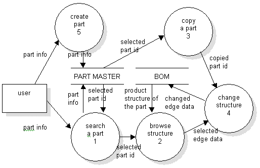
User Case(Synario)
- Select a part of which product structure is interesting.
- Browse its product structure.
- Create a new part.
- Change the product structure with the new part.

Fig 13-1. The DFD (Level 1) for the management of the part master and the product structure
STEP 3. Data modeling
- consider elements in data storage in the DFD and input/output data flow, controls in IDEF0 as candidate data entities
- draw an entity relationship diagram(s) or an IDEF1X for defining the data including data dictonary and its relationship
example:

Fig 13-2. The ERD of the system
Entity Specficiation
/* Part Entity */
ENTITY PART;
part_id NUMBER;
part_no STRING;
part_version STRING;
part_name STRING;
status STRING;
UNIQUE part_id;
UNIQUE part_no, part_version;
END ENTITY;
/* Edge Entity */
ENTITY EDGE;
edge_id NUMBER;
parent_part PART;
child_part PART;
qty NUMBER;
UNIQUE edge_id;
END ENTITY;
STEP 4. Database schema design
- specify a logical schema design, rough applicatin design with database query statements
example:
- select part_id from part where part_no = '16500100' and part_version = '---';
(see Process 01 in the Fig 13-1 DFD) - select b.part_id, b.part_no, b.part_version from part a, edge b
where b.parent_node = input_part_id
and b.child_node = a.part_id
(see Process 02 in the Fig 13-1 DFD)
* need application programs to recursively execute the query - copy the selected part_id into main memory.
(see Process 03 in the Fig 13-1 DFD) - add : insert into edge(edge_id, parent_node, child_node, qty) values ( new_id, selected_part_id, copied_part_id, 1)
cut : delete edge where edge_id = selected_edge_id
replace : cut the old_edge
add the copied part with the parent part of the cut part
(see Process 04, 05 in the Fig 13-1 DFD)

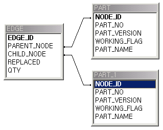
Fig 13-3. The database schema of the system
Queries corresponding to the applications
STEP 5. Schema validation
- evaluate functionality with database instantiation and evaluation query and check integrity for the entity, referential and user-defined
example:
- known selected_edge_id
- known copied_part_id
- insert edge(parent_node,child_node,qty) values(select parent_node from edge where edge_id=selected_edge_id,copied_part_id, 1);
- delete edge where edge_id = 'selected_edge_id';
STEP 6. Application design and shcema modification
- develop a specification(s) for the applications through the state transition diagram
- modify database schema considering application HW/SW environment
- consider real implementation of the specfied integrity through user interface, menu structure, triggers,.etc.
example:
-
EDGE EDGE.replace(PART new)
{ new_id = NEW ID();
pid = self.get_parent_node();
cid = new.get_node_id();
old_edge = self.get_edge_id();
archive(old_edge);
return (NEW EDGE(new_id,pid, cid,old_edge);}
void PART.explosion()
{
self.print_part();
select child_node from edge where parent_node = self.get_part_id();
for ( child_node )
{ child_node.explosion();}
return;}
Knowledge & Engineering Databases (c) copyright Namchul Do, 2000